Exploration of Chosen Concept
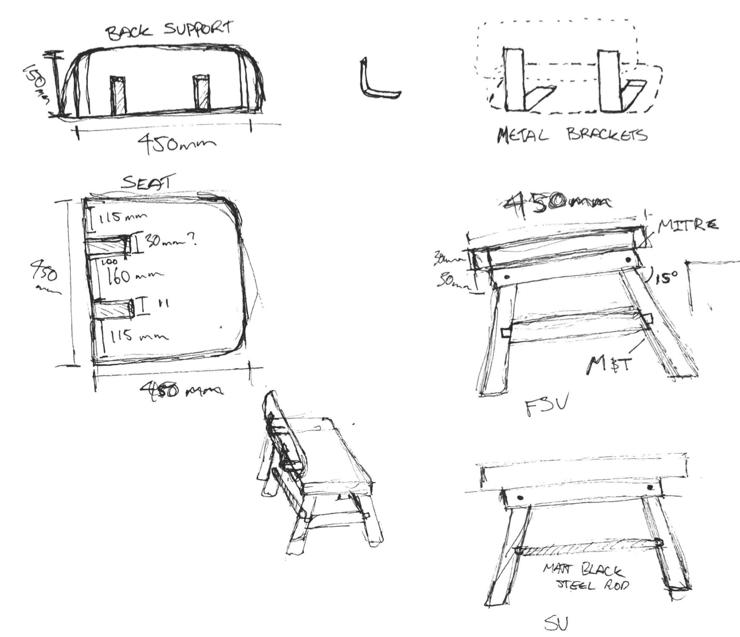
In these sketches, I decided to explore the ways in which i might be able to incorporate the mortise and tenon joint in order to fulfil the required criteria for assessment. I began by experimenting with a foot rest on my stool, though my intentions were to make my stool one that was on the smaller side of the limitations, and so the practical use of the foot rest would be lost. i also explored the use of a steel rod as a foot rest to the same conclusion.
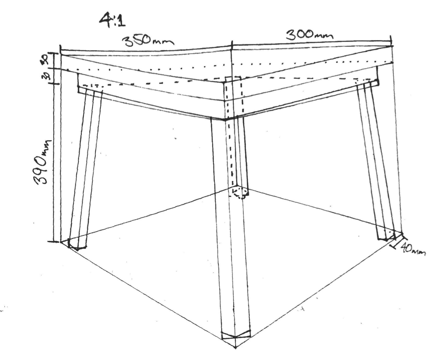
Also seen is the inclusion of the tapered legs to 15° in order to provide stability and reaching the wider edges of the stool footprint.
Annotated Perspective Drawing
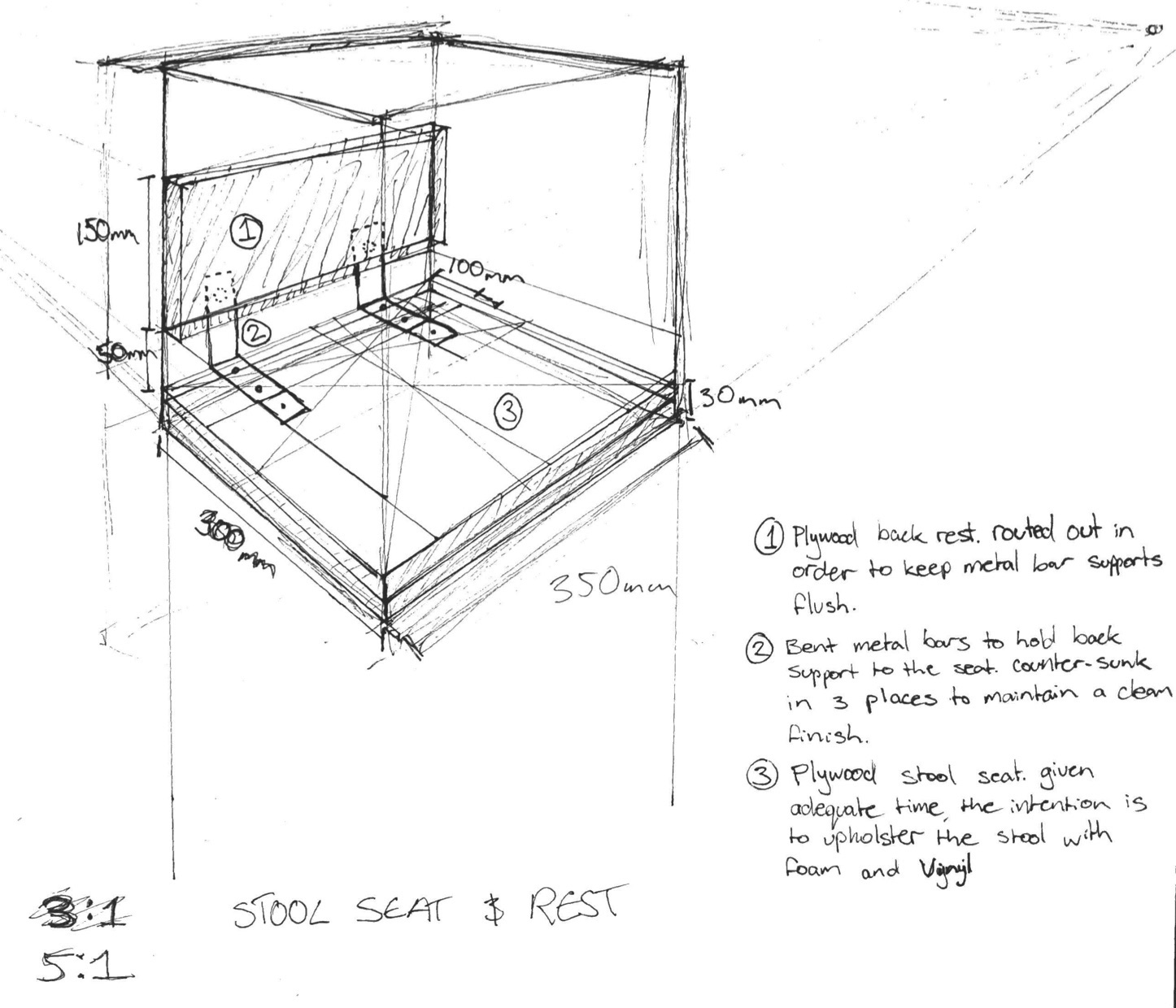
Joining Processes and Details
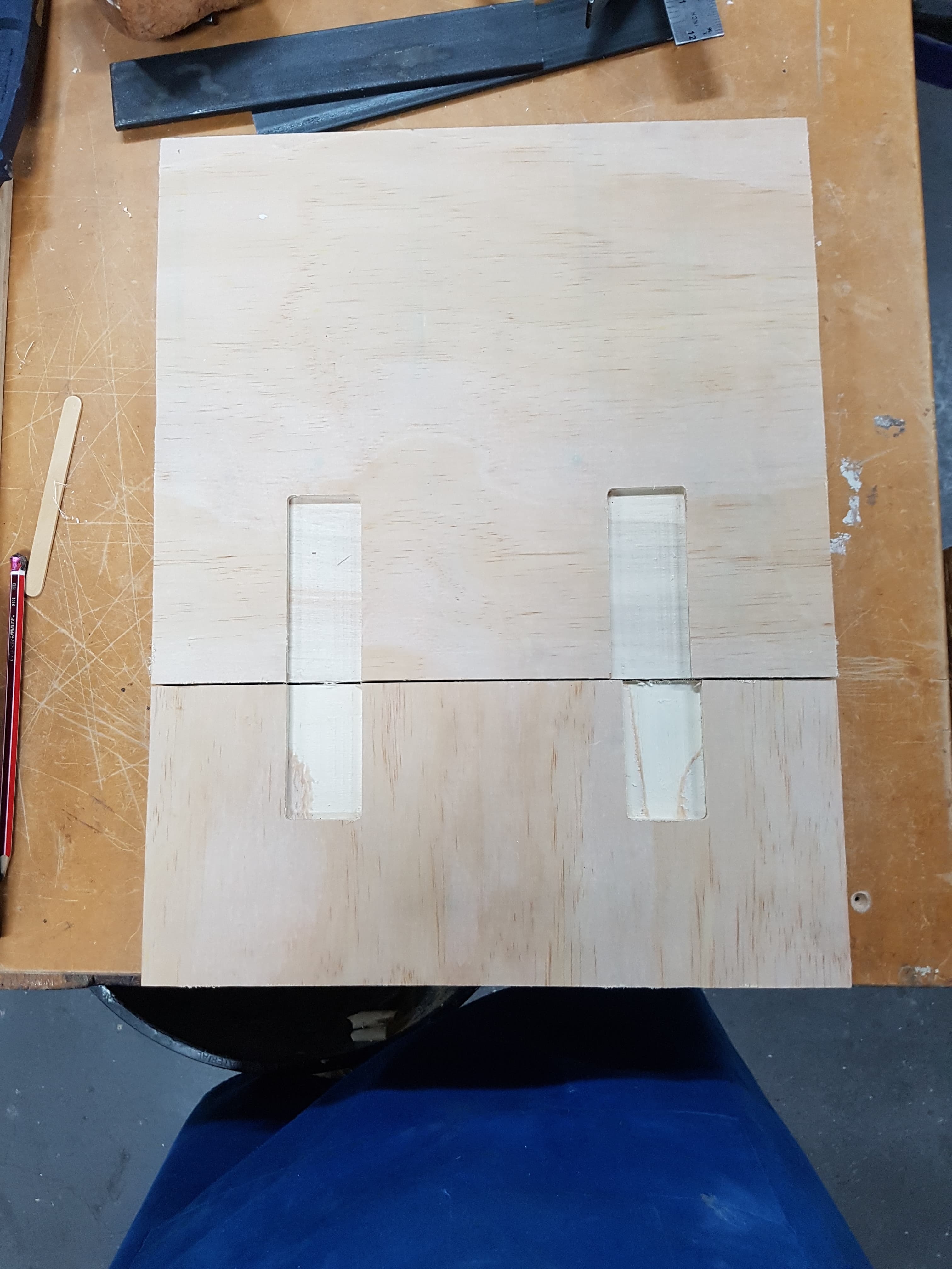
1. Leg and Seat Mortise and Tenons
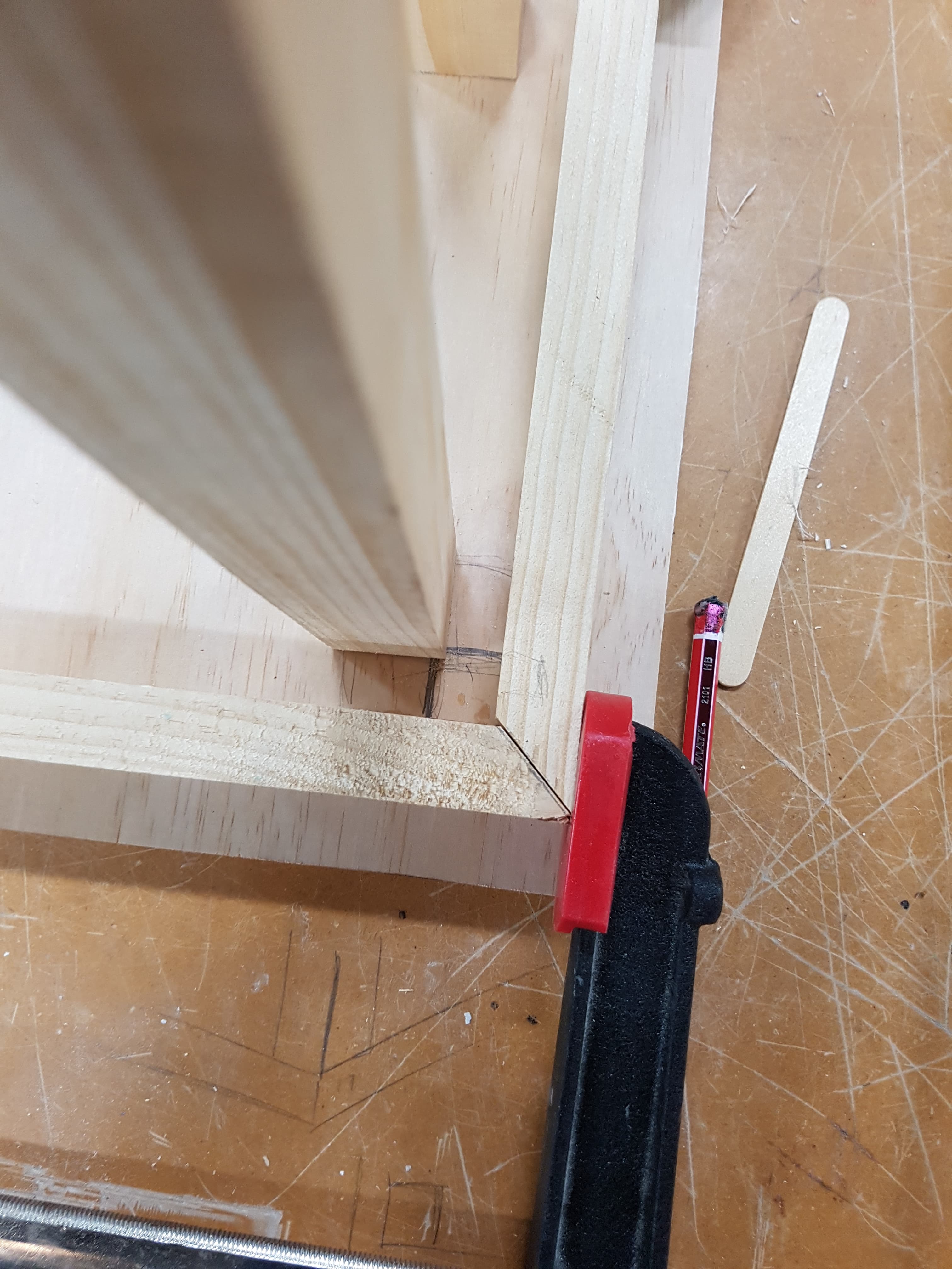
2. Mitred Frame
3. Frame Doweled to Legs
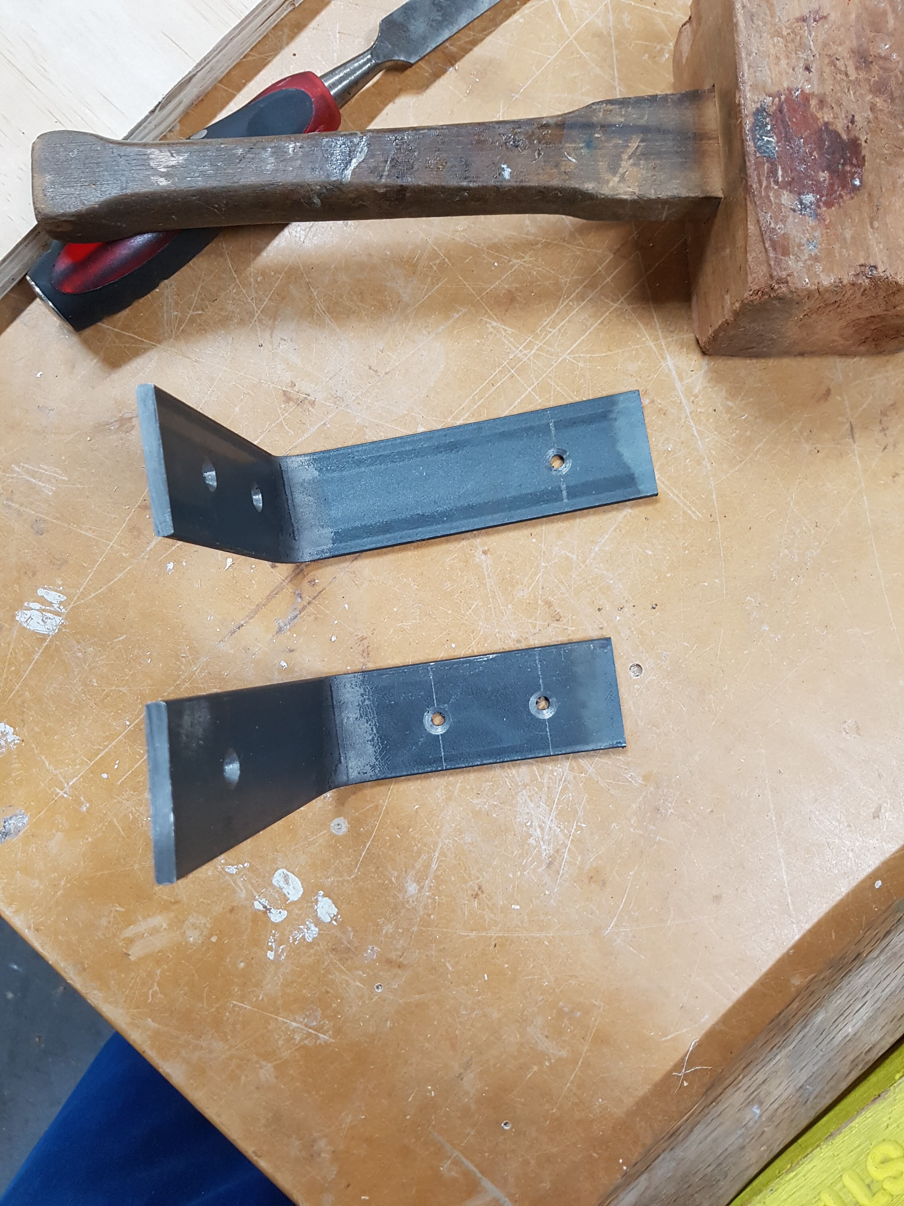
4. Counter-Sunk Steel Brackets and Screws
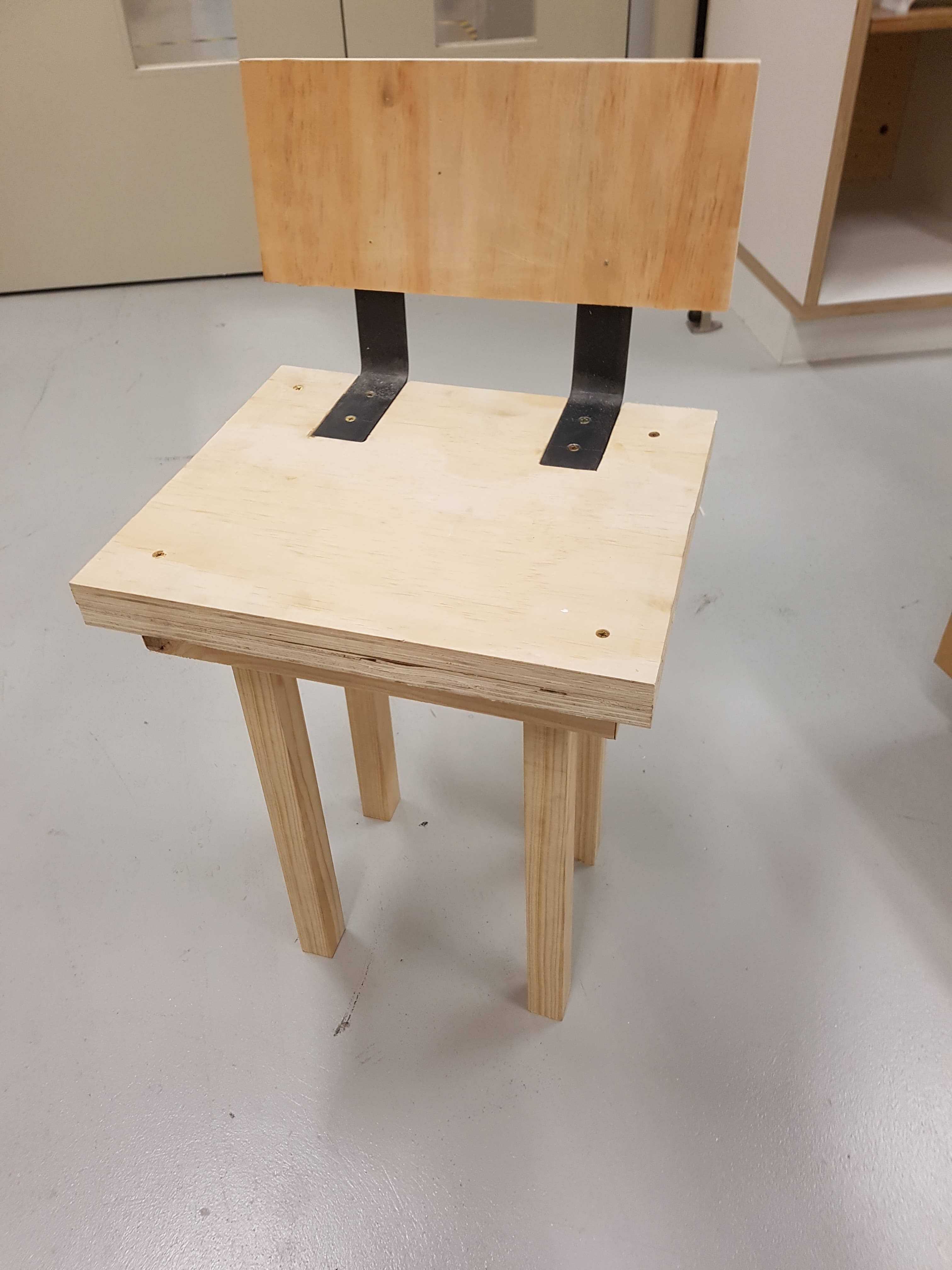

Making Process
1. CNC file for stool seat and back rest
2. Cutting lengths of timber for each element of the stool
3. Cut the mitres of the frame for around the stool legs under the seat
4. Determine the angle that the tenons will have to be cut at in order to fit the mortises at a slant and cut appropriately
5. Glue mitred frame to underside of the stool and fit stool legs into CNC-cut mortises. drill holes through the frame and legs for dowels to fit through
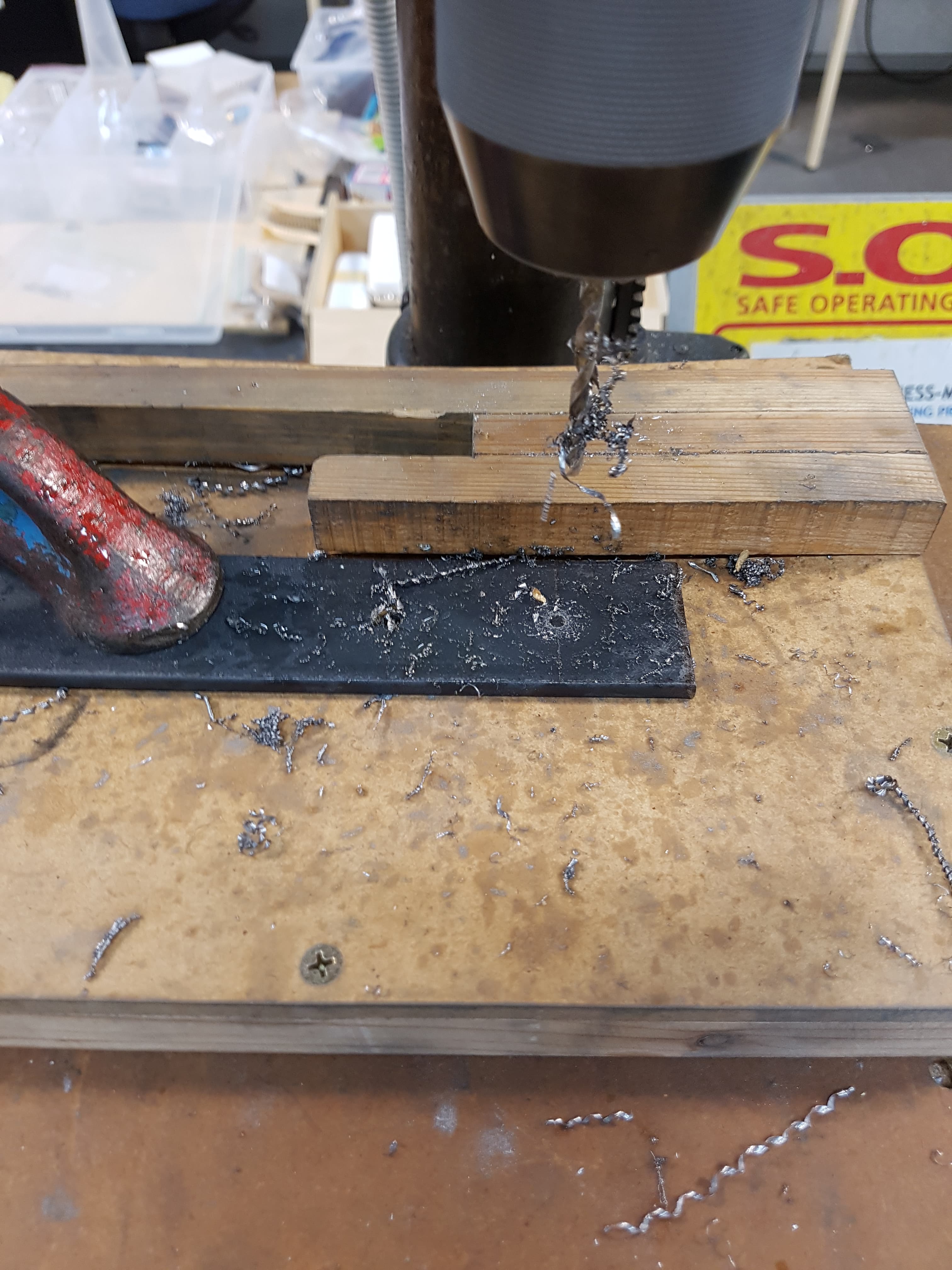
6. Cold form steel flat bar to ~100° angle and drill counter-sunk holes in order to attach to the stool seat
7. connect back rest to the stool seat by screwing the steel brackets to each piece
Changes to be Made
1. Edit CNC files in order for metal brackets to fit flush without need for chiselling and realign the spots that the brackets will fit.
2. Counter-sink the metal brackets on the appropriate sides.
3. Use thicker timber for the legs in order to stable the connection against the mitred frame and provide the opportunity for a hidden dowel to provide further stabilisation.
4. Upholster seat for comfort and to cover connecting screws on the seat top.
